Introduction to Passive Optical Networking
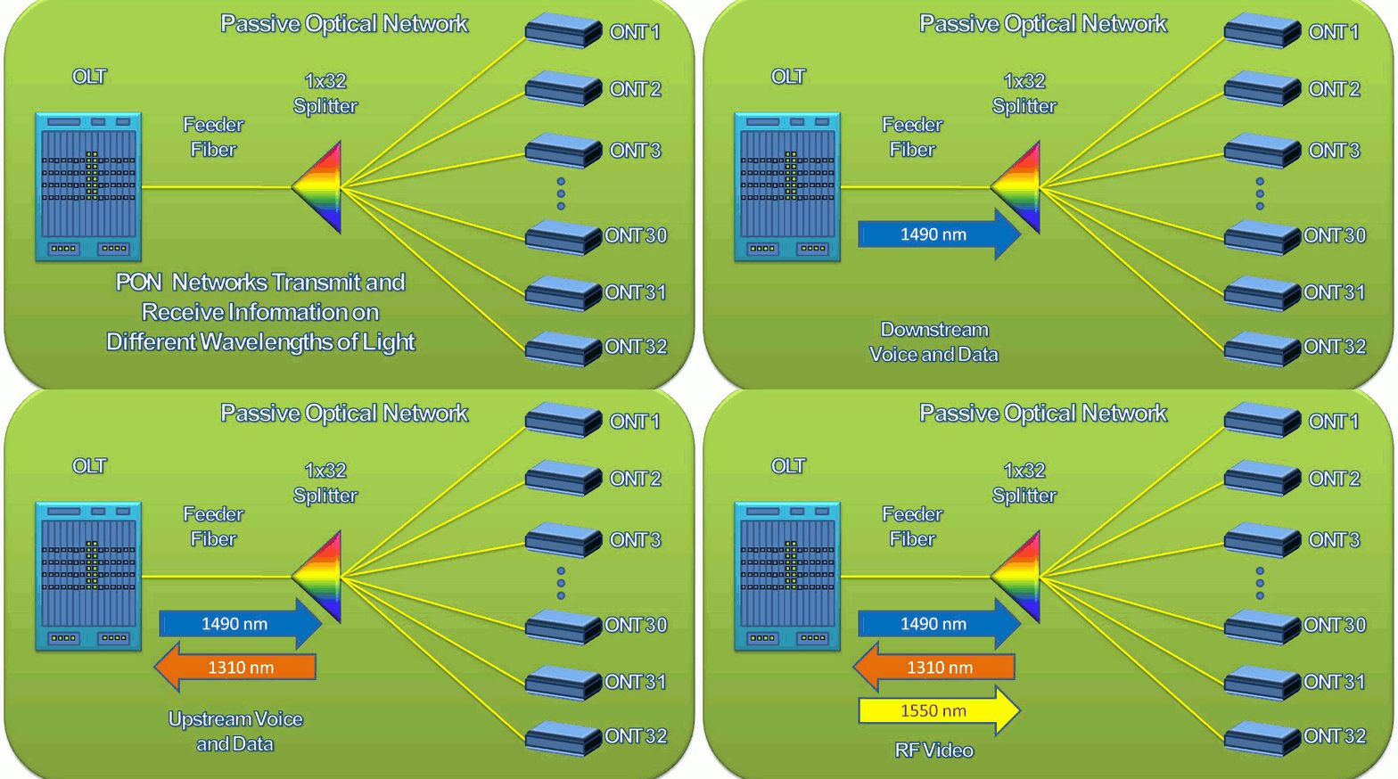
Passive Optical Networks (PON) are standards-based communication architectures. There are literally tens of millions of subscribers utilizing PON for voice, video and data service (known as "triple play" service). PON networks rely on wave division multiplexing (WDM) and lasers to provide triple play services in an efficient and future proof service offering. WDM involves the use of multiple wavelengths or "colors" of light emitted from low power communication lasers to propagate signals downstream to end users as well as another separate wavelength for upstream communication to the service provider's central office. In this way, PON systems do not require a protocol to control the flow of transmitted data versus received data. The receivers and transmitters are "tuned" to a specific wavelength and thus are "blind" to the other wavelengths present on the PON.
Optical Line Terminal
PON systems are composed of five primary components. The first component is the Optical Line Terminal or OLT. The OLT serves as the head-end of the subscriber network and typically resides within the service provider's central office facility. The OLT connects to the service provider's core networks for voice and data services and one OLT chassis is capable of connecting as many as 2000 or more subscribers. The lasers in the OLT and the downstream subscriber equipment are capable of transmitting 12 to 40 miles depending on the type of PON hardware in service, the number of fibers being served, and the quality of splices and connectors in the fiber network between the central office and the subscriber. The OLT chassis is a scalable system having card slots which are hot-swappable for ease of service and maintenance. These card slots accomodate PON cards, each of which provides 2, 4, or as many as 8 PON ports for connection to downstream fibers. It is important to note that because the PON system utilizes WDM technologies, there is no need for a pair of fibers to each port. Instead, a single, single-mode fiber (SMF) connects to each PON port. OLTs must be designed to be very reliable due to the number of customers being served by a single chassis. The power supplies, processors, and Ethernet switch cards within the chassis are often able to be deployed in redundant pairs to ensure service availability.
Feeder Fiber
The second component in a PON network is the feeder network. This is simply the individual fibers which connect to the OLT's PON ports. The typical number of feeder fibers is 56 to 64 depending on the type and whether the chassis is fully equipped with PON cards. These feeder fibers will distribute from the central office below ground and distribute for as many as 5 to 10 miles where they enter the neighborhoods being served. At this point the feeder fiber may have transitioned to an above ground or aerial installation. This is typical in older neighborhoods and the fiber will simply be hung below the existing metallic telephone lines on the utility poles. The total number of fibers serving a neighborhood will depend on the subscriber density of the area and will often include a small percentage of overbuild (excess fiber) of perhaps 5 to 15 percent.
Optical Splitter
At this point you may be somewhat confused by the number of subscribers being served from a single OLT. With only 56 to 64 PON ports per chassis, how can the feeder fibers provide connections to thousands of users? These numbers are possible to the passive optical splitter. The term "passive" refers to the fact that the splitter requires no power as opposed to an "active" device like the OLT. The splitter serves to optically replicate upstream signals to a number of downstream fibers. The typical number of fibers served in a PON network is 32. These 32 fibers represent the subscriber connections in the distribution network while the input fiber represents one of the feeder fibers connecting to the upstream OLT. As the splitter provides a replicated optical signal to all 32 subscribers downstream, it is simultaneously combining those 32 fibers into an single feeder fiber in the upstream direction. Consequently the optical splitter is sometimes referred to as a splitter/combiner. The splitter will be housed in a ruggedized fiber distribution hub (FDH) which serves to protect the splitter and the numerous fiber connectors serving the subscriber homes. For more information on how a splitter is constructed and the various types of PON splitters, refer to our tutorial on that subject.
Distribution Fiber
The portion of the fiber network downstream of the optical splitter is known as the distribution fiber. The distribution network comprises the one-to-many aspect of a passive optical network. This is the portion that typically is cost prohibitive for many service providers to deploy. This is largely because of the labor intensive effort to distribute the fiber along the right-of-way in subscriber neighborhoods and businesses as well as the hardware required to terminate and protect the fiber along this path. The distribution fiber often terminates into smaller groups along a street which may represent a fiber count of between 1 and 12 fibers which may then be routed from the street to the subscriber home where it connects to the optical network terminal.
Search site:
Advertise here


